
| SinusLeistungsSteller - electronic battery switch (EBS) |
|
December 2012: Here we want to introduce first prototypes(!) of the the new Electronic Battery Switch (EBS) . (Why is this device so important ? This can be read here: motivation/description The EBS is mainswitch and fuse in one device - it weighs about 100g and with (77x42x18)mm dimensions its pretty small. The main contacts are realized with robust M8-screw-blocks. The unidirectional 200A-version (EBS-60-200DC) has a forward resistance of only 1 mOhm (measured from contact to contact; the Rdson of the internal MOSFETs are typically about 0,6 mOhm). For spreading the heat losses, the EBS makes use of the same cooling concepts as the SLS and cSLS. If needed, mounting on a heatsink is possible. If the device overheats, because of bad or missing cooling, the module protects itself by instantly turning OFF the main current. The main current is measured and continously compared with preset threshold. Shutdown threshold of the fuse can be adjusted (potentiometer bottom/left) and responds accurately within a few micro seconds. Even a short circuit on the load side results with prompt shutdown without noticable sparks. Of course, we will also provide a version with hard wired trigger threshold (without a potentiometer). 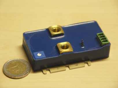
The control takes place over a galvanic insulated control input. Because of this potentialfree interface, the EBS can be used as a High- or as a Low-side switch. The ON-control circuit (pin 3,4) operates with a constant current of about 20mA at a voltage from 8V upto max. 60Vdc. It is possible to obtain auxiliary voltage from the main battery (as shown in the connection diagram below) or over other (even potential-free) sources. The internal constant current supply allows the connection of a LED to display the ON-/OFF-state. Since a constant current is flowing, no LED-resistor is required over the entire voltage area from 8..60V. More than one LED can also be connected in a row. In that case it is important to notice that the lower switch threshold increases in accordance with the forward-voltage of the added LEDs. The error-output (pin 1,2) also operates in the voltage area from 8..60Vdc and also limits the current to about 20mA. With a simple LED (no resistor is needed!) it is possible to signal the electronic fuse set-off. The error current circuit is insulated (galvanic) towards the load circuit and also towards the ON-control circuit. 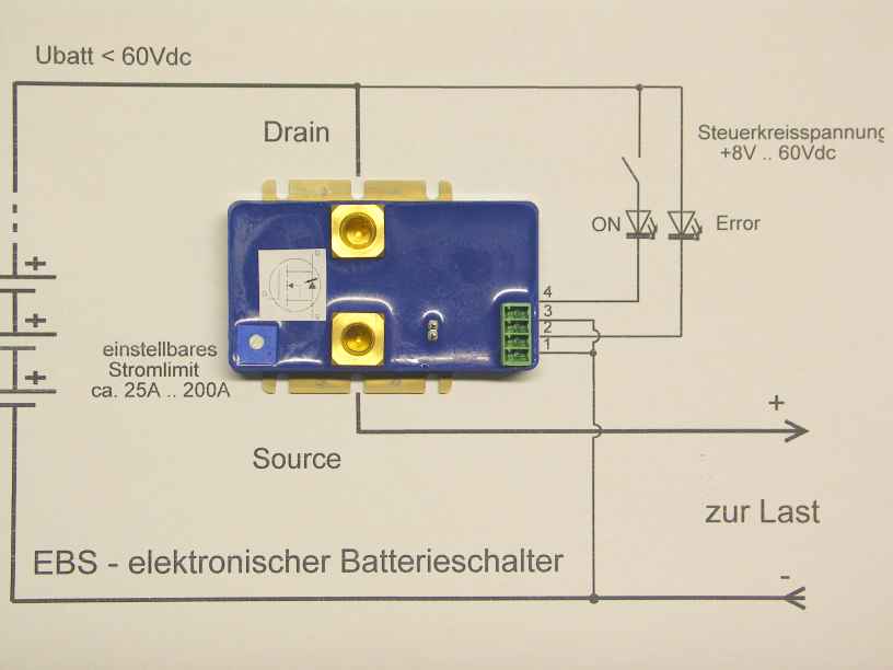
The inductance of the supply line is important for the switch-off behaviour. On the one hand, this effect of this inductance is desired to limit the current-slope in short circuit situation. On the other hand, the line inductance stores energy by W=0,5*L*I², where the current enters by square! - additionaly it can become quite large at short circuit! This (large) energy needs to be dissipated, when turning off the MOSFETs and therefore may not exceed the "Avalanche Energy" specified in the data sheet. It is therefore necessary, to limit the line inductance (which means cable length) both downward (=minimum cable length) and upward (=maximum cable length). The images below are showing measured signals of main current (red, 50A/Div), voltage over EBS´mains (blue, 20V/Div) and Power (grey, 2kW/Div) one with L=2µH (above, steep current increase) and one with L=10µH (below, slow current increase). In the left column EBS is turned on with already shorted output - in the right column EBS is turned on and after that the short circuit at the output occures. 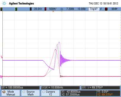
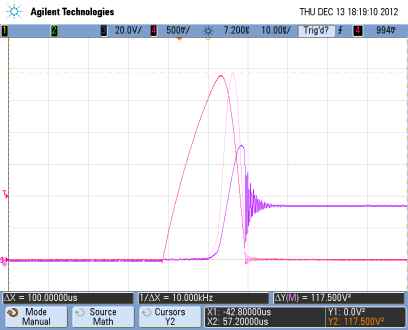
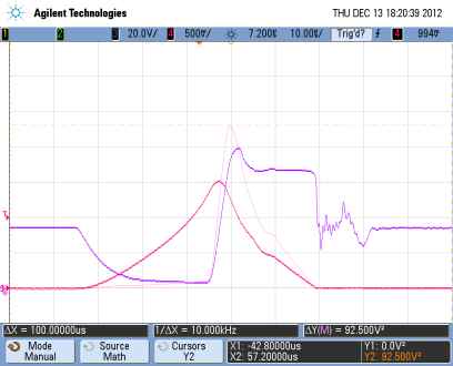
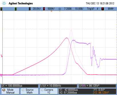
In all 4 signal curves (with same timebase of 10µs/Div) a current overshoot over the trigger threshold of the electronic fuse (preset to 100A) can be seen. This is result of a short delay introduced by the switch driver. At small L and short circuit after turning on (image top/right) the current overshoot (I_peak=280A) as well as the power turn off (P_peak=11,75kW!!) is biggest and so represents the most critical case. Fortunately the allowed range for line inductance meets most real life situations. Converted to permissible cable lengths it covers a range from 2m upto 20m. A variant with integrated Sollwertgeber (SG) is also available. This option makes sense e.g. to all battery-powered vehicles, which needs a direct manual speed presetting by the driver/pilot. 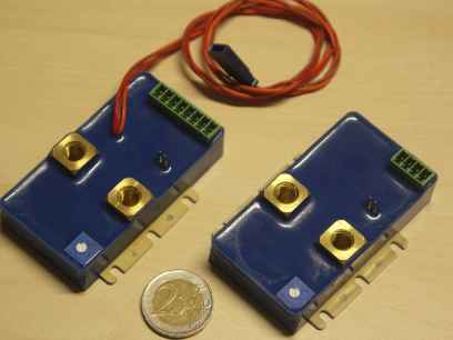
The interface of the Sollwert potentiometer is realized by an extension of the control circuit connector (green). The 3-pole servo-signal-output comes out directly off the potting. The other functions are identical to the EBS-basic module. The integrated Sollwertgeber is supplied from the ON-control circuit and therefore is switched ON/OFF together with the EBS module. 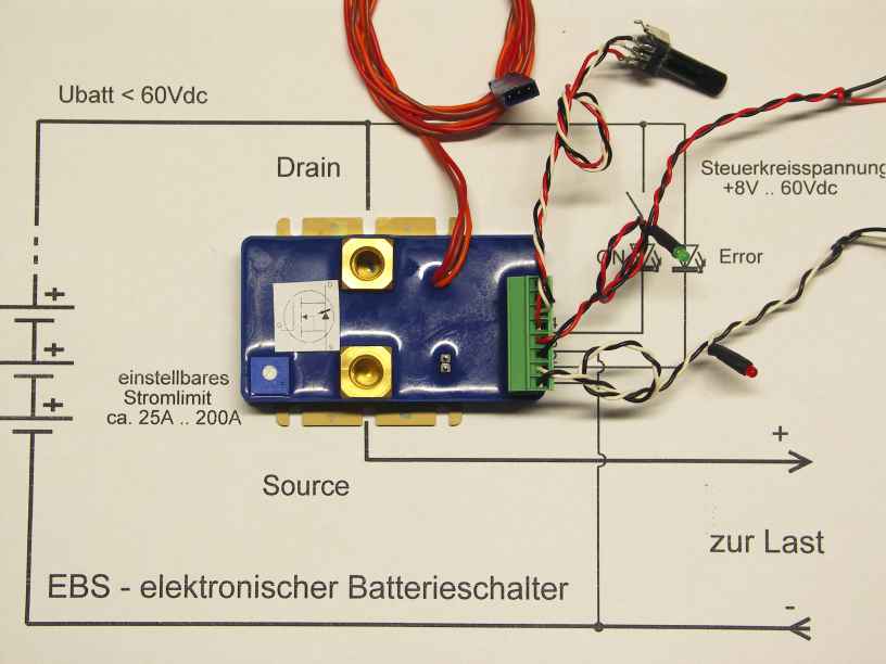
... tbc! ... a bidirectional EBS-module with 150A (with 2 antiserial switched MOSFETs) is also under construction and will be tested soon. We will provide additional information on this here ... |